The in-vehicular network in a modern car is complex and composed of multiple Electronic Control Units (ECU) that communicate with each other using different protocols. Most ECUs found in the car of today are communicating using the Controller Area Network (CAN) vehicle bus standard. All ECUs placed on a CAN bus can read all the messages by all the ECUs on that bus. If the in-vehicular network would consist of a single bus, it would result an inefficient and insecure in-vehicular network. For example, it is a secure idea to prevent the complex ECUs with a remote attack surface (e.g. infotainment) to send messages directly to the vehicle’s power train or brakes. Therefore, it is standard practice in modern cars to implement a gateway, which is responsible for connecting different separate CAN buses, and applying message filtering. The network is typically accessed through the Data Link Connector (DLC) which is standardized (i.e. OBD-II) on most vehicles. At Riscure we are analyzing the security of a modern car for which a simplified representation of the in-vehicular network is shown below.
This blog post is part of Riscure’s ongoing Automotive Security research. The results of this research are implemented in Riscure’s tools, services and training for the automotive market. Check out our latest offers: Riscure Huracan automotive security test tool for developers and security teams, Riscure Security Services for Automotive and the Embedded Security for Automotive training program.

To understand the vehicle under evaluation better we like to understand what messages to send to the different ECUs in order to initiate specific actions. In principal, the gateway has access to all the messages send on all CAN buses. Therefore, we set out to create a proprietary cable that is capable for sniffing all the messages sent through the gateway. We have two major requirements:
- Sniffing – The Multi CAN bus Logger must be able to sniff all the CAN buses at the same time. Time stamps must be added in order to create a coherent log that can be used to track messages sent from ECU A to ECU B and vice-versa.
- Sending – The MCBL must be able to send CAN bus messages on arbitrary CAN buses.
There is commercial tooling available to support sniffing and sending on multiple CAN buses at the same time. For example, there is tooling available from Vector, which is used by the automotive industry extensively. We did not take this approach for two reasons: it is expensive and low-level control is most likely limited. However, there are advantages of using professional tooling, there is typically mature software delivered with the hardware and you can get support. We believe we need low-level control of our sniffer in order to implement other functionality in the future (e.g. Man-in-the-Middle attacks).
We considered two approaches: create our own board designed around a Microcontroller (MCU) or repurpose a current solution. We decided to repurpose a commercial solution offered by comma.ai, which also focuses on reverse engineering vehicles in order to retrofit their co-pilot solution. The Panda OBD-II Interface dongles support up-to 3 CAN buses and are easily available. The Panda dongles are designed around a STM32F413 MCU. Its firmware is open source and published on Github. Therefore, we have full control over the firmware and making modifications is a blessing.
We need to be able to plug the Panda dongles on the gateway’s connection in order to sniff them. We created a cable that we can place between the gateway and the connector going into the gateway. This allows us to connect the CAN buses of the Panda dongles to the CAN buses of the gateway without affecting the original connection. With this cable in place, we can still drive the car. A logical representation of the cable’s design is below.

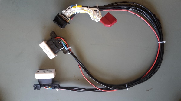
Riscure’s awesome lab personnel implemented our design with high quality connectors and pins. Their craftsmanship resulted in a professional looking cable that is robust enough to drive around with without feeling unsafe. It is always a good idea to realize you placed your own hardware and software at a critical location in the in-vehicular network. We do not want to jeopardize our own safety too much. The cable is shown below.

The cable allows us to sniff and send on six CAN buses at the same time. The Panda dongles support a connection via USB, Bluetooth and Wi-Fi. We prefer to use a physical connection, as it is faster and more robust. We created a flexible Python tool that logs all communication observed by the Panda dongles, including time stamps, using multiple standard formats. This includes the formats used by commercial vendors like Vector, Intrepid and our own Riscure Huracan. In addition, we can interpret and visualize the logged communication data using open source tools like Busmaster and SavvyCAN. We show an example output using these tools below.
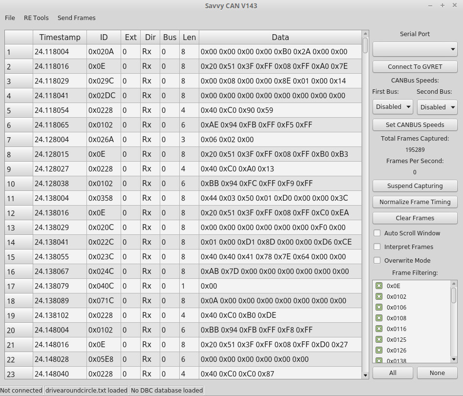
Now we have a physical cable and software to visualize the CAN bus communication observed in the vehicle under evaluation. To give you an idea about the amount of data, we log roughly 20k messages per second on the modern car we are analyzing. Our next challenge is to make sense of this significant amount of communication data.