
Our TEE Security investigation
The goal of our tee security investigation was to assess how strong Samsung’s TEE OS is and whether it can be compromised to obtain runtime control and extract all protected assets, allowing, e.g. decryption of user data. We did not consider a full exploit chain and instead focused on the TEE only, assuming an attacker already in control of the Android environment.
This series of posts is an addendum to the presentation we had at Riscure’s Workshop in September 2020 about secure Tee’s:
- In the first post, we will introduce TEEs, TrustZone and TEEGRIS.
- In the second post, we are going to investigate vulnerabilities in TAs running in TEEGRIS, and we will exploit one TA to get runtime control.
- In the last post, we will show how to further escalate privileges and gain access to the full TEE memory.
If you want to learn about common security pitfalls in the TEE development, check out our whitepaper now.
Trusted Execution Environment (TEE)
A Trusted Execution Environment aims at providing a secure environment for the execution of security critical tasks such as payment, user authentication, and user data protection.
The secure Tee environment is isolated from the non-secure or untrusted environment called Rich Execution Environment (REE) – in our case, the Android OS (note that in the rest of the posts, we will use the terms REE and Android interchangeably). A TEE OS is usually made of a kernel, running at a high privilege level, and multiple applications called Trusted Applications (TAs) with fewer privileges. TAs should be isolated from each other and from the TEE kernel such that a compromised application cannot compromise other applications or the TEE kernel. In short, there are three types of separations that a robust TEE is expected to implement:
- Separation between TEE and REE.
- Separation between TAs and TEE kernel.
- Separation between TAs.
To achieve these security requirements, a TEE requires support from hardware primitives to enforce separations. The cooperation between the hardware (HW) and the software (SW) is critical and is continuously required.
A secure TEE consists of a number of components, these are:
- TEE aware hardware.
- A robust Secure Boot chain for initializing the TEE software.
- A TEE OS kernel to manage the secure world and trusted applications.
- Trusted applications to provide the functionality to the REE.
In our blog posts, we will mostly look at items 1, 3 and 4 – and assume that the secure boot process is correctly implemented by the platform. We will also assume an attacker in control of the REE (and therefore that can communicate with the TEE) that wishes to compromise the whole TEE.
TEE kernels generally expose a very limited interface to the Android OS, and normally most of the functionality is implemented by TAs. Therefore, our plan is to first find an exploitable vulnerability in a TA and then escalate to the kernel from there. But before jumping to a disassembler, let’s first take a look at ARM’s extension used to implement TEEs: TrustZone.
ARM’s TrustZone
The TrustZone technology is a hardware architecture developed by ARM that allows the software to execute in two domains: “secure” and “non-secure”. This is achieved by the use of an “NS” bit, which signals whether a master is operating in “secure” mode or “non-secure” mode. A master can be, for instance, a CPU core, but also hardware peripherals such as a DMA or a crypto engine. Whether a master is secure or not can either be hardwired in the design or configurable; for instance, a CPU core secure status can be switched by invoking an SMC instruction (more on this later) or by toggling the “NS” bit in the “SCR” register.
To define the access restrictions for slaves (such as peripherals and memory), TrustZone usually includes two components, named TrustZone Address Space Controller (TZASC) and TrustZone Protection Controller (TZPC).
The TZASC can be used to define secure ranges in DRAM. ARM provides a couple of different implementations; the most recent is called “TZC-400”. The following figure presents a high level overview of how it is normally implemented in an SoC, as shown in its technical reference manual.
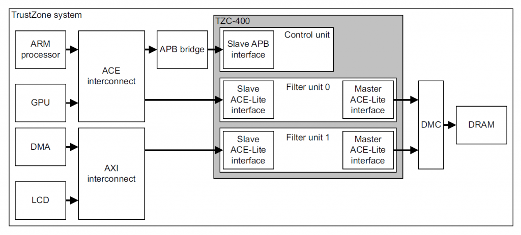
Schematic representation of a Trustzone system.
Figure 1. TZASC high level overview
As can be seen, any DRAM memory access goes through the TZASC before being forwarded to the memory controller. The TZASC can decide based on an internal set of rules whether the memory access is allowed or not.
The TZASC contains a base region (region 0) that is always enabled and spans the whole DRAM memory range. A number of other secure regions are then defined for which the access can be restricted. More specifically, for other regions, the following can be set:
- Start and end address
- Secure read and write permissions. These permissions will be applied to any secure master that tries to access the memory range. Note that the TZASC has no concept of execute permissions and enforcing that is delegated to the MMU.
- Non-secure ID filtering: Regions can be configured to allow access to non-secure masters. In the case of the TZC-400, a bit-mask can be specified for both read and write permissions to have fine grained control over which non-secure master is allowed to access the memory range.
The TZPC implements a similar concept but applied to internal peripherals and SRAM instead of external DRAM. It contains one register (R0size) that is used to specify the size of the secure on-chip SRAM in steps of 4KB. This offers less flexibility compared to the TZASC, as it only allows defining one secure region and one non-secure region: the secure part starts at 0 up to the specified size, and the remaining SRAM will be considered as non-secure.
A number of additional registers are then present to specify for each peripheral whether they are secure (so they can only be accessed by secure masters) or not. The mapping of which bits in the TZPC registers correspond to which peripherals is not defined, and it is fully specific to each different SoC.
Normally, most of the settings for the TZASC and TZPC are configured during initialization and never change. However, some of them need to be dynamically modified at runtime. One example of this use case is the Trusted User Interface (TUI), used for performing secure payments. When a user needs to enter their PIN to authorize a payment (e.g. in the S10 when using Samsung Pay), the TEE takes over and directly controls the display and the touch sensor. The idea is that since the PIN is a sensitive asset, the TEE handles the whole process instead of the untrusted Android OS making it more secure. Therefore, it has to reconfigure both the display and the touch controllers as secure using the TZPC so that even an attacker with kernel-level code execution in Android cannot read out the PIN. Displaying images on the screen requires a secure frame buffer stored in DRAM, therefore the TEE will also use the TZASC to reconfigure a portion of DRAM as secure and use that as the frame buffer. Once the user finishes entering the PIN, the TZASC and TZPC are restored to their previous values, and Android takes over again.
Transition between secure TEE and REE
The transition between secure/non-secure modes is managed by a component called “secure monitor”. This monitor is the primary interface between the TEE and REE and is the only component that can change the security state of a core.
As in the REE, the TEE maintains a user mode/kernel mode separation between the kernel and TAs. The TEE OS is also responsible for loading TAs and passing parameters between the REE and TAs and also between TAs. TAs run in the user space of the secure world and provide services to the REE.
ARMv8-A CPUs support four privilege levels for each “world”, also known as exception levels:
- (S-)EL0 – user mode/app
- (S-)EL1 – kernel
- EL2 – hypervisor
- EL3 – Secure Monitor
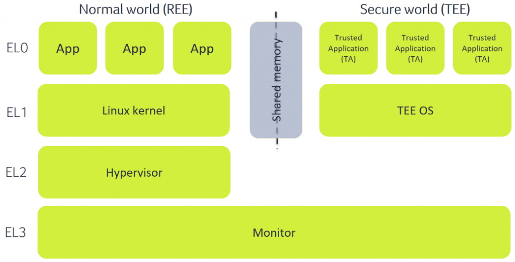
Schematic representation of the transition between a Ree (normal world) and a secure tee.
Figure 2.
In the REE, we have Android apps running at EL0 with the Linux kernel running at EL1.
EL2 only exists in non-secure mode (before ARMv8.4-A) and is referred to as the hypervisor. It was initially designed as a way to handle multiple virtual environments running at lower privilege levels in parallel, but in Android environments, it usually is used as a kernel hardening mechanism. In Samsung phones, this is also the case. The hypervisor component is called Real-time Kernel Protection (RKP), and among other uses, it limits the memory accessible by the kernel and makes some kernel structures read-only to increase the difficulty of exploiting the kernel. In part 3 of our series, we will provide more details about the RKP.
Finally, we have the secure components, which are the targets of our investigation: EL3 (which always runs in secure mode), S-EL0 and S-EL1. There can be several paradigms on how a TEE is implemented, but by far, the most common one is by having a very small component running at EL3 that is in charge of switching between the two worlds, a fully-fledged kernel running at EL1 and several TAs running at EL0. Samsung’s TEE OS TEEGRIS is no exception and adopts this design.
While a fully isolated environment would be very secure, for it to be practically useful, it needs to communicate with other untrusted components running in Android. Communication between the REE and the TEE is triggered using a dedicated instruction named “Secure Monitor Call” (SMC). This instruction can be invoked by both worlds at EL > 0, which means that Android applications cannot directly initiate communication with the secure TEE. What normally happens is that the Linux kernel acts as a proxy and exposes a driver that can be used by apps to interact with the TEE. This design has the advantage that access restriction policies (e.g. using SELinux) can be applied for accessing the driver so that only a subset of apps can communicate with the TEE, restricting the attack surface. This is also the case for the S10, in which only a limited number of applications and services are allowed to communicate with the TEE.
Note that for the rest of our investigation, we assume an attacker who has the capability of communicating with the TEE. This is the case in a phone rooted using tools such as Magisk, and it can otherwise be achieved by obtaining runtime control of either the Linux kernel or any of the Android apps and services that are allowed to communicate with the TEE.
Once the SMC instruction is executed, an interrupt is generated in the secure monitor running in EL3. The SMC handling mechanism routes the SMC to a component to handle and process it. If the monitor can process the SMC directly, it does so and immediately returns. Otherwise, it forwards the request to the TEE kernel (running at S-EL1), which can then process it internally or further forward it to a TA running at S-EL0.
Now that we know how TrustZone works at a high level let’s analyze Samsung’s implementation.
TEEGRIS tee
TEEGRIS is a relatively recent TEE OS, introduced by Samsung on the Galaxy S10. Most of the newer (starting from 2019) Samsung phones that have Exynos chipsets will also have TEEGRIS running in the TEE.
Before the introduction of the S10 in March 2019, Exynos chipsets used a different TEE OS, called Kinibi and developed by Trustonic. A lot of excellent research was done on this OS, reported, for instance, in these blog posts [2][3][4]. However, with TEEGRIS being a relatively new OS, not much public information is available. In fact, the only available information we were able to find is contained in this blog post, which gives a nice introduction to TEEGRIS and its kernel and mostly explains how to set up QEMU to be able to fuzz it. Even though for our investigation we decided to only focus on reverse engineering, the post still contains useful information such as the boot image layout (where TEEGRIS is stored) and an explanation on how to identify syscalls handled in the kernel.
Starting from this information, let’s take a look at the main components of TEEGRIS: the kernel, TAs and drivers. Note that as explained earlier, the monitor code has a very important role in TrustZone, however, in Samsung’s case, it is stored encrypted in a flash. Therefore we did not analyze it, and instead, we focused on the other components, which are instead stored in plain text.
TEEGRIS kernel
The TEEGRIS kernel is a small component running in secure EL1. Even though it is small in size, it is not exactly a microkernel, and for instance, it integrates a number of drivers that can be used by TAs. It runs in 64 bits mode and supports both 64 bits and 32 bits TAs and drivers running in user space. Since the kernel is stored in plain text in the boot partition, it can be easily extracted and disassembled.
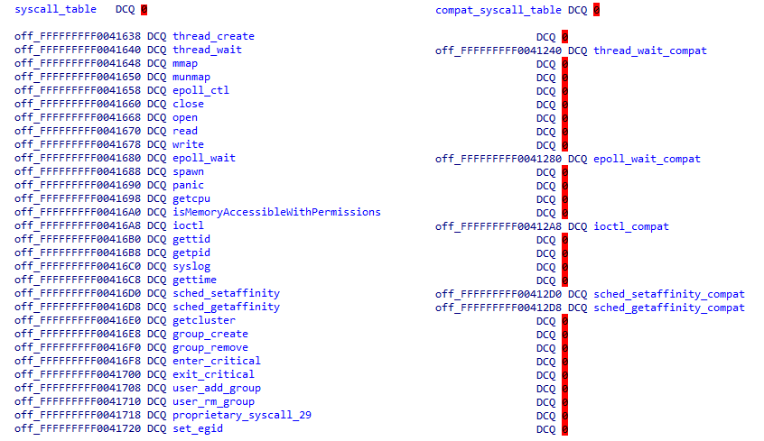
In the Aarch32 syscall table, only syscalls that have a different implementation in Aarch32 are present
The kernel implements a number of POSIX compatible syscalls, with the addition of a couple of TEEGRIS specific ones. Conveniently enough, Alexander Tarasikov, in his post, noticed that there are wrappers around syscalls implemented in two shared libraries (see the TA section below for a description of how shared libraries are handled): libtzsl.so and libteesl.so. This allowed us to quickly identify two tables in the kernel containing syscall handlers for both 64 bits and 32 bits TAs:
Figure 3. Aarch64 and Aarch32 syscall tables. In the Aarch32 syscall table, only syscalls that have a different implementation in Aarch32 are present
Analysis of the syscalls implementation showed that Samsung makes thorough use of two routines that are probably well known to people familiar with the Linux kernel: copy_to/from_user. These routines are used to access data coming from user-land to make sure that TAs cannot reference internal kernel structures:
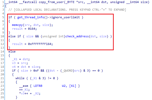
Figure 4. copy_from_user decompiled code
The code in Figure 4 first verifies if a flag is set to ignore any other check. The flag is used when syscall handlers are invoked directly by the kernel with known safe arguments. If set, this function is just a wrapper around memcpy.
In all other cases, the code invokes check_address, shown below:
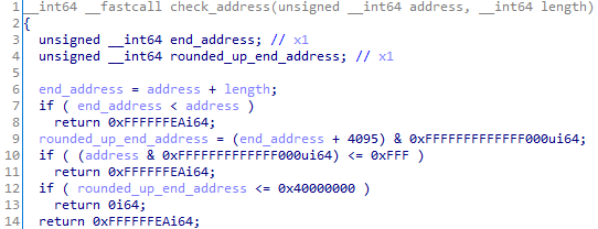
Figure 5. Address check routine
The piece of code shown in Figure 5 gave us some important information: the first page of a TA should never be mapped, as checked in line 10 (probably as a protection against NULL pointer dereference), and a valid TA address should be smaller than 0x40000000 (line 12). Anything higher than that will be considered invalid and discarded. Also, as shown in Figure 4, notice that the copy is performed using LDTR* instructions. LDTR* behave the same as regular LDR* instructions but cause the memory access to be performed with EL0 privileges. This is because PAN is enabled, and even though the check_address function might miss some edge cases, any unprivileged access to kernel memory will cause an access violation.
The upper limit of 0x40000000 for the TA address space also means that the possible randomness for ASLR is relatively small – especially considering that 64 bits TAs are supported. To confirm if this hypothesis is true, we looked for how TA images are loaded. Note that in TEEGRIS, TAs are (slightly modified) ELF files, therefore we can easily follow the code to look for functions that parse the standard ELF format. We ultimately ended up in function “map_elf32_image” (an equivalent one is present for 64 bits TAs as well):
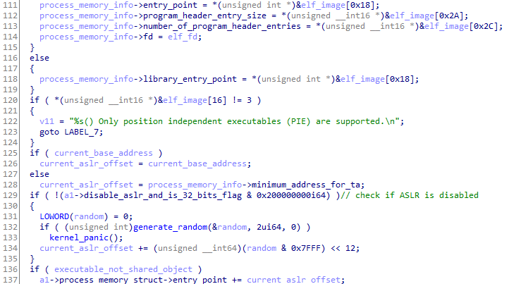
Figure 6. Randomization of code and data segments
Notice that the code enforces that only PIE executables can be loaded (line 120). Afterwards (line 132), it generates a 2 bytes random, masks it with 0x7FFF (line 134) and uses it as a page offset to be added to the entry point (and the base address, done later in the same function). This means that the ASLR offset can have only a maximum of 32768 values, and it is applied to all the segments specified in the ELF.
Dynamic memory (used, e.g. for the heap and mapping memory shared with the REE) is instead randomized in the “spawn” syscall using a different value but with a similar method:
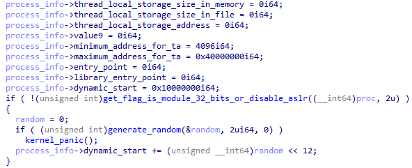
Figure 7. Randomization of dynamic memory
Note that ASLR is not only used in TAs but also in the kernel itself (commonly referred to as KASLR). We will not go into details of the implementation, however, this needs to be kept in mind if we ultimately want to exploit the kernel. In the entry function, the kernel generates another random value and modifies page and relocation tables accordingly.
As mentioned earlier, the kernel has a number of drivers built in. Drivers are mostly used for communicating with peripherals (such as SPI and I2C) or performing crypto operations.
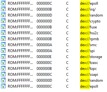
Figure 8. Partial list of drivers implemented in the kernel
As Samsung implemented TEEGRIS following POSIX specifications, the way to interact with drivers does not come as a surprise. Drivers have a name usually starting with “dev://”, and can be accessed by opening the corresponding file from a TA. Afterwards, a number of syscalls (e.g. read/write/ioctl/mmap) are available to TAs to interact with the driver. Inside the kernel, a structure is used to store the syscalls implementation for each driver.
Access to drivers and syscalls is not always granted to every TA, in fact, TAs belong to different groups, with each group having different permission levels. The kernel keeps track of which permissions are granted to each TA and performs checks to make sure that only allowed TAs can access restricted functionality. The following two figures show examples of permissions granted to two different groups: samsung_ta and samsung_drv.
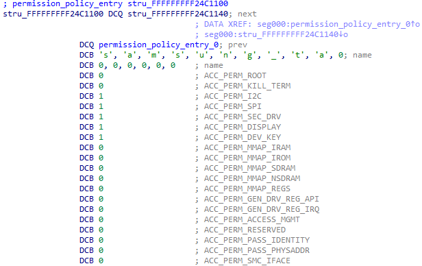
Figure 9. Access permissions for the samsung_ta group
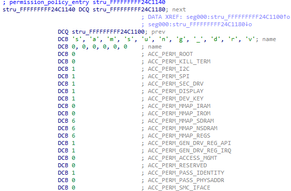
Figure 10. Access permissions for the samsung_drv group
As can be seen in the pictures, there are 19 permissions that are associated with each TA. A value of 0 means that permission is not granted, while other values grant at least partially the permission. Most of them are either granted or not, but for a couple of them (the MMAP ones), there is a specific mask to determine whether memory can be mapped with read/write/execute permissions. In these two examples, the samsung_ta group is fairly limited and has access to only a couple of permissions, while the samsung_drv group has more rights. Other groups are available in the system with different sets of permissions, but these two are by far the most common ones.
TAs and user-land drivers
Now that we have a high-level overview of how the kernel works and how to interface with it let’s take a look at TAs. Normally, there are two paradigms for including TAs in TEEs: either they are an immutable blob that is bundled with the TEE OS and always loaded at initialization time, or they can be loaded at runtime by Android. Samsung took a hybrid approach with TEEGRIS, and both options are supported and used.
The boot partition includes a special archive (called startup.tzar) that contains all shared libraries that are needed by TAs and a few special TAs and drivers that are required by the system at an early stage, before Android is fully booted: TSS (used for managing shared memory), ACSD (a driver to support TA authentication) and root_task (used to load TAs and verify them in combination with ACSD). Binaries that are part of the tzar archive are standard ELF files and can be directly loaded into a disassembler for analysis. Since the archive is part of the boot image, its signature is verified at boot time.
TAs can also be loaded at runtime from Android. Loadable TAs are stored in the /vendor/tee and /system/tee partitions. In the S10, there are about 30 different loadable TAs that have the following format:
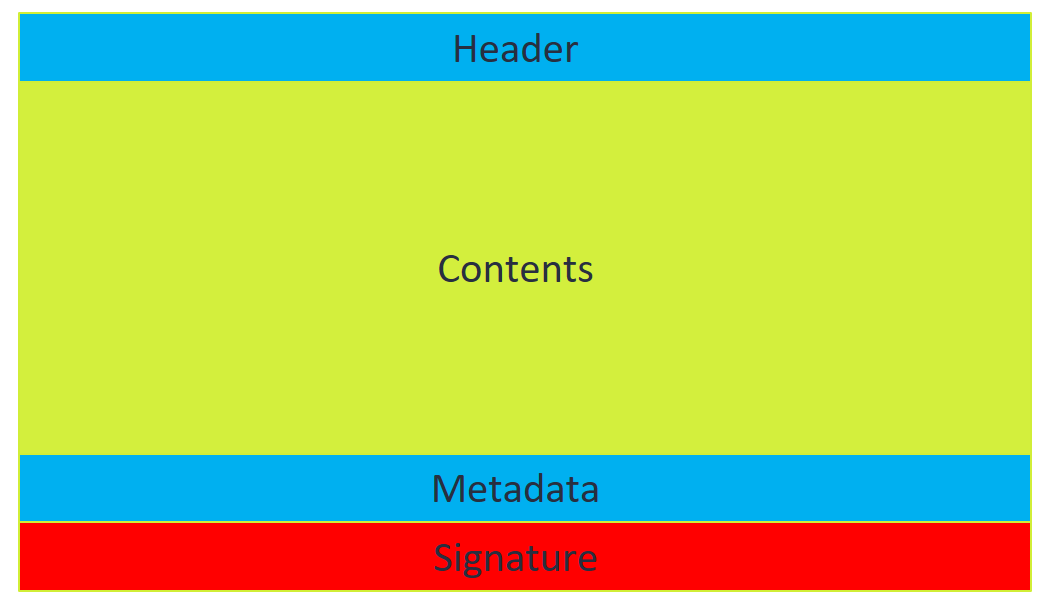
Figure 11.
- The header is 8 bytes long and contains a 4 bytes version (either “SEC2”, “SEC3”, or “SEC4”) and the length of the content section.
- The content section is a regular ELF file with the actual TA contents. If the TA is of type “SEC4”, the contents are encrypted, otherwise, they are in plain text.
- The metadata section contains the TA group. From version “SEC3” onwards, there is an additional field containing a version number. This version is used by the root_task in combination with ACSD to manage TA anti-rollback protection. Whenever a SEC3 or SEC4 TA is loaded, the version number is extracted and compared to a version stored in the RPMB storage. If it is lower, the TA cannot be loaded, and an error is returned. If it is higher, the version number in RPMB is increased to match the TA version so that older copies of the same TA cannot be loaded anymore. This also means that from this point on, SEC2 versions of the TA will not work. This functionality is crucial for revoking old TAs with known vulnerabilities, and we will look at this in more detail in part 2 of our series.
- The signature section contains an RSA signature over the rest of the image. It follows the X.509 format, and it is parsed by ACSD.
From this short description, it is clear that loadable TAs can be easily disassembled by removing the initial header and loading them as an ELF file into a disassembler. The only complication would be when the SEC4 format is used (as the ELF is encrypted), however, in practice, only SEC2 and SEC3 are used in the Galaxy S10 and S20. TAs can then import libraries from the tzar archive. Libraries are also regular ELF files and implement C library functions plus the Global Platform (GP) API and TEEGRIS specific functionality.
TAs in TEEGRIS implement the GP API (whose specifications can be found here), which specifies 5 interfaces that a TA needs to implement to be able to interact with the REE:
- TA_CreateEntryPoint, invoked when the TA is loaded.
- TA_OpenSessionEntryPoint, called when a Client Application (CA), in our case, Android apps, running in the REE first establishes a connection to the TA.
- TA_InvokeCommandEntryPoint, which contains the main command handler that will be invoked for each command sent by a CA. This is where most of the TA functionality will be implemented.
- TA_CloseSessionEntryPoint, called when a CA closes a session with the TA.
- TA_DestroyEntryPoint, executed when the TA is unloaded from memory.
Even though a TA is an executable, its execution is a bit convoluted since the actual main() function is inside the libteesl.so library. When a TA is launched, the following actually happens:
- The start() function inside the TA is executed. This function is usually just a wrapper around main():
Figure 12. Example of a start() function
- The main function is actually not inside the TA, but in the libteesl.so library. This is where most of the logic that communicates to the REE via the TEEGRIS kernel is configured. A standard POSIX epoll-based mechanism is set up for communication with the root TA. In the following snippet, the main function first invokes TA_CreateEntryPoint(), and then jumps to start_event_loop():
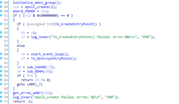
Figure 13. Snippet of the main function in libteesl
- Within start_event_loop(), the library will then receive events that represent, e.g. requests coming from a CA. The events can then be forwarded to the appropriate GP API entry point.
This section is called “TAs and user-land drivers”, but until now, we mostly discussed TAs. So, where are the drivers? Well, drivers are the same as TAs. They have the same format, implement the same GP API, but they call a TEEGRIS specific API named TEES_InitDriver. This function allows a driver to specify the driver name and a structure that can be used to interact with user-land drivers in a similar way as with kernel-land ones. User-land drivers do not have any special permissions by default, but they usually belong to groups that are highly privileged.
Exploit mitigations
To conclude the analysis of kernel and TAs, let’s summarize the exploit mitigations that are implemented in the kernel and in TAs. Some of them were already introduced earlier in the kernel analysis – here we will present all of them:
- XN (eXecute Never) is used in both kernel and TAs. This means that data memory is never executable, and code is never writable.
- Stack canaries are used in the kernel and in TAs to protect against stack-based buffer overflows.
- ASLR and KASLR are implemented to randomize the address space of TAs and kernel.
- PAN and PXN are in place to prevent the kernel from accessing or executing user-mode memory.
Historically, exploit mitigations in TEE OSes have been lackluster compared to other modern OSes. Previous exploits on Samsung’s TEE targeted old phones that only included XN as a countermeasure, and as such, there were fewer mitigations to bypass. Therefore, the S10 is a step forward in the right direction, and a full attack that aims at compromising the whole TEE will need to chain multiple vulnerabilities.
Communicating with TAs
Now that we know a bit more about TAs, we need to find out how to communicate with them from the Android environment. Fortunately, the GP standard not only defines a set of APIs for TAs, but also for CAs that want to communicate with TAs. Each of the entry points described above have a corresponding call that can be used by CAs (e.g. TEEC_OpenSession can be used to open a session, TEEC_InvokeCommand to send a command and so on).
For TEEGRIS, a library named “libteecl.so” implements the GP API, so communicating with TAs is as simple as using dlopen/dlsym to resolve the symbols needed for the GP API. To open a session, the UUID of the target TA needs to be specified. The library will then look for a TA with that UUID in /vendor/tee or /system/tee (the UUID is the file name) and pass the whole TA image to the TEE, which will then authenticate and load it. All is done transparently to the CA, which is not aware of how the actual communication happens.
Note that, as we mentioned earlier, not every Android app is allowed to communicate with the TEE. It is worth reiterating that there are restrictions in place, and a full-chain exploit would first require an attacker to obtain runtime control of an application that can talk to the TEE.
What’s next?
This concludes the first part of our blog post. In the next part, we will show how we identified and exploited vulnerabilities in a TA, which allowed us to gain runtime control within the context of the TA. In the final blog post, we will show how this can be leveraged to escalate privileges and compromise the whole TEE.
References:
[1] https://developer.arm.com/documentation/ddi0504/c/
[2] https://medium.com/taszksec/unbox-your-phone-part-i-331bbf44c30c
[4] https://blog.quarkslab.com/a-deep-dive-into-samsungs-TrustZone-part-1.html
[5] https://allsoftwaresucks.blogspot.com/2019/05/reverse-engineering-samsung-exynos-9820.html